Sidebar
Table of Contents
Use Case 2: Tactical Microgrid Standard (TMS)
Details
| Author | Daniel Herring |
|---|---|
| Title | Associate Staff |
| Organization | MIT Lincoln Laboratory |
| Date | 28 May 2020 |
| Time | 31 Minutes |
| Presentation | Tactical Microgrid Standard - DDSF BrightTalk |
| Document | Tactical Microgrid Standard |
Tactical Microgrid Standard (TMS) Using DDS for Secure Communications
Abstract
A proposed Tactical Microgrid Standard (TMS) is a new power grid system architecture, developed to meet Department of Defense (DoD) and industry needs. TMS offers unique features that address challenges faced by existing power systems. Data Distribution Service (DDS) provides resilient and secure publish/subscribe communications for TMS. The presenter, Daniel Herring has used DDS for 14 years at MIT Lincoln Laboratory and shares some experience on what DDS enables and how DDS can be introduced to other organizations.
Attribution
DISTRIBUTION STATEMENT A. Approved for public release. Distribution is unlimited.
This material is based upon work supported by the Department of the Army under Air Force Contract No. FA8702-15-D-0001. Any opinions, findings, conclusions or recommendations expressed in this material are those of the author(s) and do not necessarily reflect the views of the Department of the Army.
(c) 2020 Massachusetts Institute of Technology
Delivered to the U.S. Government with Unlimited Rights, as defined in DFARS Part 252.227-7013 or 7014 (Feb 2014). Notwithstanding any copyright notice, U.S. Government rights in this work are defined by DFARS 252.227-7013 or DFARS 252.227-7014 as detailed above. Use of this work other than as specifically authorized by the U.S. Government may violate any copyrights that exist in this work. See definition for Defense Federal Acquisition Regulation Supplement (DFARS).
The Need for New Power System Architectures
The Tactical Microgrid Standard (TMS) is a new proposed standard for power systems. TMS was developed to lower costs and increase performance for the Department of Defense (DoD), private industry, and residential users. As illustrated in Figure 1, power grids face a range of increasing challenges:
- Natural disasters of increasing frequency and impact
- Man-made interference or malicious attacks
- The inclusion of new technologies that produce and consume power
- Better integration of components to provide system-level behaviors
TMS applies the following design principles to Smart Grid applications:
- Simple – require less expertise, planning, and time
- Efficient – get the most out of every drop of fuel
- Resilient – get the most out of every piece of equipment
- Modular – loosely coupled building blocks that can be assembled to meet changing requirements
- Scalable – grow in size over time
- Extensible – grow in features over time
- Open architecture (OA) – support a wide range of manufacturers and product lines

Since the advent of the Electric Grid, our society's dependence on electricity has grown and it is now an essential utility. For example, electricity powers the internet technologies that are so essential to modern society. A rare power outage lasting a second, minute, hour, or day may be tolerable. Frequent outages or ones lasting a week, month, or year would cause significant social and economic harm. Some recent, high profile instances of power losses due to natural disasters are hurricanes, earthquakes and fires (i.e., New Orleans, Puerto Rico1) and California2)).
In addition to the natural disasters, there are an increasing number of man-made disasters that have or potentially have caused power outages. Some examples of man-man disasters are the planned power outages in Northern California created by the power company to try and prevent wildfires caused by downed power lines.3) There are also malicious attacks caused by malware injected into power system components. An example of this malware attack occurred in the Ukraine.4). The overall trend is that our reliance on electricity will increase over time and the magnitude of the damaged cause by power outages will also increase.
Furthermore, there is a need for better ways of integrating power systems. We want to accelerate the release of new technologies, reduce costs, and increase automation between devices, all at the same time.
As a consequence, this has driven for a lot of new requirements for utility infrastructure. There are hundreds to thousands of companies working in the energy sector and they need a common platform to facilitate integration of their solutions. TMS meets this need for a wide range of on-site power use cases.
Canonical Power System Architecture and for Overall Power Missions
Figure 2 provides a graphic overview of what a “generic” power grid system looks like.
Grid Components:
- Power Sources are large generators of electricity that use traditional energy resources such as as coal, oil, natural gas and nuclear as well as reneable resources such as solar and wind (not listed in graphic).
- Power Transmission is the network of high voltage lines (cables) that connect sources to electric substations, where it is dropped to medium voltage.
- Heavy Industry includes high-power consumers such as furnaces, electrolysis, and smelting 5)
- Power Distribution is the network of medium voltage lines that connect electric substations to most consumers.
- Consumers are the normal light industry loads and residential neighborhoods.
- Off-Grid applications have on-site power generation capabilities and may not be connected directly to utility power. They are self contained. This isolation can be due to remote operating location or by design to protect mission critical services from attacks through the utility.
In addition, there are some cross grid component functions:
- Supervisory Control Plain that coordinates the Power Sources, Transmission and Sinks. The Control is an integrated set of Supervisory Control and Data Acquisition (SCADA) applications along with human operators sitting in control rooms making decisions while in contact with other operators usually over phones.
- Disaster Response needs to span the whole system from the Power Sources to the Sinks. Some examples of disasters that require coordinated responses from Federal Emergency Management Agency (FEMA), United States Army Corps of Engineers (USACE), or some other agency are hurricanes, tornadoes, dam breaches, earthquakes, bridge failures, etc. Closely related to Disaster Response are humanity assistance missions in other regions of the world. Within the US, the Joint Chiefs of Staff, Foreign Humanitarian Assistance covers these situations. 6)
- Critical Infrastructure Operations in the US, refers operations conducted at specifically designated Critical Infrastructure Sectors whose assets and networks are vital to the US security. Some examples are military bases, a hospitals, or some other community center that needs special hardening, so if there is a disaster or failure on the grid at large, that location can continue to operate undisturbed.7)
- Fuel Underpins the entire power grid and is used directly in electrical poer generation but also heating.
- Forward Deployed Operations might be a military Base in a remote part of the planet for example, a desert, jungle, or mountainous region. It might also be a military base in a more urban or suburban site were there is already a utility grid but there is a need to be off the grid capabilities either for critical infrastructure reasons such as in the case of an attack.

The Tactical Microgrid Standard (TMS) is primarily developed for tactical systems that are categorized as forward deployments. These Forward Deployment Operations are the focus this Use Case study. However, the benefits of the TMS are not restricted to tactical off-grid operations and the adoption and adaption of the TMS to non-tactical situations is encouraged. TMS has many technological similarities to the other application scenarios. In fact some of the first implementation of the TMS are in the area of Critical Infrastructure Operations describe above.

Background of Tactical Microgrids for Forward Deployed Operations
A bit more background on the Off-Grid Use Case. Figure 4 represents an example of a Microgrid at a Forward Operating Base. In this example, there a few dozen tents on a site with potentially hundreds to thousands of people engaged in the operations. This single base site is power by multiple generation sources, has its own power distribution network and has diverse and physically distributed loads. The base is war fighter owned and operated and is self-sufficient and self-contained. It is important to note that each Forward Operating Site has a unique situation including its specific mission, goals, needs and geographic location. However, the sites share a lot of similarities in terms of power generation, transmission and load. (i.e., they are all Microgrids). Some common loads include Communications, Sensors, Weapons and least interesting but actually the post power goes to Climate Control (i.e., bases in extreme climate conditions require keeping people comfortable and equipment operating within the allowable environmental specifications.)

Tactical Forward Deployed Operational Loads
A Tactical Forward Deployed Operational needs everything that a traditional power utility has in its Electric Grid but made harder because of the on-site capabilities. This presents many operational and physical challenges the power utility do not have.
Some examples of issues that the Tactical Forward Deployed bases have that utilities do not have are:
- Rapid Deployment - Forward Deployed Bases can have rapid set-up and tear-down the base. A utility might take months or years to plan and make a change, here they make changes in minutes
- Operator Training - Forward Deployed Bases have multi-tasking generalist operating and maintaining the system 24/7 rather. Utilities might have a staff of dedicated, well trained, professional specialists monitoring and operating the system
- Dynamic Loads - Forward Operating Bases loads come and go with little rhyme or reason. The Utility has stable, predicable loads, from one day to the next you can predict loads. Here are the Transients at a utility might see a few percentage point changes in a day, but at the forward Operating Base, everything might turn on or off within minutes.
- Equipment Failures - Forward Operating Bases have higher rates of equipment failures due to maintenance or attacks.
- Organic Growth - Forward Operating Bases can grow organically by changing sources, transmission and loads depending on the mission and the dynamic priorities
- New Technology Insertion - Forward Operating Bases need to grow or shrink over time or insert new technologies such as solar over new generations of equipment
The TMS was targeted to solve these classes of problems.

Tactical Microgrid Architecture Options
Before TMS
There were four existing Microgrid architectures evaluated for developing the new TMS. These architectures are represented in Figure 6. The following is a discussion of the four architectures:
- Spot Generation - is very simple architecture and the DoD started using it around World War II (WWII) and purchased a lot of inventory during the Vietnam War. This is a typical approach today. Its simple to setup. When a tent needs power, simply setup a generator outside and run a cable into the tent. The Spot Generation is also is very inefficient because it uses a lot more generators than are needed. Often the generators tend to idle a much of the time resulting wasted fuel. The Spot Generation architectures are fairly fragile since when a generator fails, the power in the tent go out resulting in the loss of mission functionality for that tent.
- Consolidated Generation attempts to improve on the inefficiency of Spot generation, by running distribution cables to multiple tents. it does improve efficiency by better matching the load to the source, however, this kind of optimization ends up being more complicated and adding more mission functionality losses if a generator fails. As a result, it is not widely used. [daniel]I want to add the term officially here because I'm sure that the creative field engineers will do this if one generator fails and just "tap into" another generator
- Central Microgrid locates all the generators in one location and then fans out all the power through a Transmission Network to all the tents that require power. The Central Microgrid combines the positive characteristics of the Spot and Consolidated Generation into a single architecture by providing some backup generation capabilities. For example, extra generator(s) can be located on the site providing redundancy to protect against generator fails by balancing the power production to the extra generator(s). Unfortunately, there is even more dependent on cables om the Transmission Network. Another drawback is that Central Microgrids available in the market place today require one vendor for all generators at a site meaning that you can not mix and match across generators from different companies or even within product lines from single company due to issues in communication control as well as other aspects of how the system function. There are some actual deployments available in the marketplace today, the Advanced Medium Mobile Power System (AMMPS) Microgrid is being deployed in the DoD inventory with a 2019 purchase another $0.5B worth of available equipment.
- Distributed Microgrid is attractive because it has the efficiency of the Central Microgrid but also has redundant Transmission Network cabling. In a Distributed Microgrid each generator's load is independently adjustable resulting in a more complicated control problem. Consequently, with existing technologies, it is more complicated to setup and has more proprietary vendor lock-in. Note: in a Central Microgrid, all the generators must support an equal fraction of the load.
In summary, Figure 6 graphicaly represents the Tactical Microgrid landscape before TMS.

With TMS
After the introduction of TMS, the same four Microgrid Architectures are shown in Figure 7 with updates to the traits reflecting the enhancements made by TMS.
With TMS, many of the previous issues become solutions
- TMS, by definition is an Open architecture (OA), so it directly tackles many of the proprietary vendor lock-in issues
- Anecdotal evidence suggests that TMS changes to how the system is operated and maintained make the Distributed Microgrid architecture as simple to setup and operated as the other architectures (i.e., Spot Generation, Consolidated Generation and Central Microgrid.
- TMS also improves the Microgrid resiliency by:
- Supporting redundancy in Power Sources when there are generator surpluses or redundancy
- Defining coordination protocols between the Power Sources and switching circuitry in the Microgrid's Power Transmission network
- Automating fail-over mitigation through coordination and redundancy
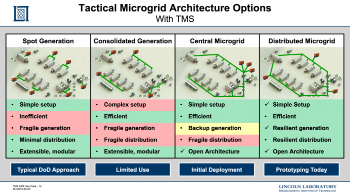 Figure 7: Tactical Microgrid Architecture Traits With TMS
Tactical Microgrid Standard (TMS) Components and Interfaces
Figure 8 shows the Components and Interfaces defined within the TMS Architecture.
Components
The major system components are:
- Control Services Component is comprised of:
- Microgrid System Manager provides a dashboard display for the operator
- Microgrid Controller provides high-level system behaviors
- Power Devices Component provides device level automation. It comprised of Power Sources (i.e., Source Units) supplying power into Power Transmission network (i.e., Distribution Units) distributing power to Power Sinks (i.e. Load Units). The Power Distribution also can provide power to optional power Storage Units devices and power Conversion Units devices which improve the capability of the overall Microgrid system.
- All these Units are mix-and-match. This means the on-site operator can pick which components and units they need (or have) and can expect to plug them together creating or maintaining a working Microgrid.
- There are few major messages going between these Control Services and the Power Devices components.
- All the Power DevicesUnits send Health and Status Messages up to the Control Services Component, and
- The Control Services Component sends Command and Control messages back down to the Power Devices Component's Units.
It is important to point out that each of these Power Devices Unitscan operate in stand-alone mode just as they did in the traditional Spot Generation or Consolidated Generation architectures. The TMS architecture can also run with Power Transmission network communications to provide Central or Distributed Microgrid capabilities. In the event of a Power Transmission network communications failure, the Units built using Distributed Microgrid fallback to internal operations and continue to operate until the network can be restored.
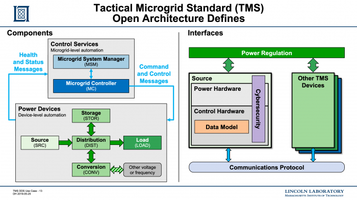 Figure 8: TMS Components and Interfaces
Interfaces
Figure 8 shows the Components and Interfaces defined within the TMS Architecture. Inside each component, unit or device, there are also a few interfaces defined at the software and hardware levels providing some modularity.
Each component has a number of external interlaces to the other components within a TMS system. The major system Interfaces are:
- Power Regulation is the key interface and is represented at the top of the Interface section in Figure 9. TMS makes no changes to the original 60 hertz 120 volts or equivalent power standards, however, TMS does add some rules for interfacing with the Control Services. For example, when there are multiple Power Sources (i.e., Source Units) , how the sources share the Power Sinks (i.e. Load Units).
- Communication Protocol is foundational interface and is represented at the bottom of the Interface section in Figure 9. TMS specifies a communications protocol used to connect the Components, which is Data Distribution Service (DDS).
Each component has a number of internal interlaces. The major internal Interfaces are:
- Power Hardware may have a life expectancy of 30+ years, however, the the computing technology can be refreshed more frequently.
- Control Hardware a key aspect of the TMS Architecture is the Data Model (DM). The Data Model describes the messages flowing back and forth, what the end points are, what the contents of the messages are, and what triggers the messages to go back and forth. Part of the Data Model are Interface Definition Language (IDL), Quality of Service (QoS), Topics, the other things related to DDS.
- Cybersecurity maps the physical identity of the hardware to the cryptographic identity stored in hardware modules. It also provides software allowing for the end-to-end trust. For example, being able to trust a power measurement coming from a known device, and is the data actually shown on the display matching and reflecting what is happening in the field. Another example would trusting the commands sent to devices are coming from authorized users and authorized Microgrid controllers.
In summary, everything on this figure is part of the TMS standard. The cyber security initial baseline is DDS SECURITY with the built in plug-in. We have plans to extend and enhance this baseline and make it available to others in the DDS Community for use in other applications.
Figure 9: TMS Components and InterfacesTactical Microgrid Standard (TMS) in Operation
TMS established an operational installation with actual Power Sources, Power Transmission and Power Sinks.
- Note: All of the networking connections are made using physical connections since within the DoD environment wireless communications are not considered reliable or secure enough.
A couple of years ago, the US Government paid to create a test TMS installation as a joint endeavor between a government organization and a private company. The installation goal was to implement TMS by upgrading a couple of dozen existing Microgrid pieces of equipment. Onse the equipment was assembled, a number of tests of disturbances were conducted. The disturbances iin the tests include:
- Rapid Deployment
- Dynamic Loading
- Growing and Shrinking the Microgrid, and
- Equipment Failures by removing a device from the middle the system without warning. Good news, we did not blow anything up.
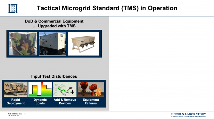 Figure 10: Tactical Microgrid Standard (TMS) in Operation
Tactical Microgrid Standard (TMS) in without TMS
Figure 11 represents a traditional Spot Generation architecture, when the Power Source (i.e., generator) stops producing electrical power, all power stops and mission functionality is interrupted. That functionality includes mission and life critical systems as well as climate control and lights.
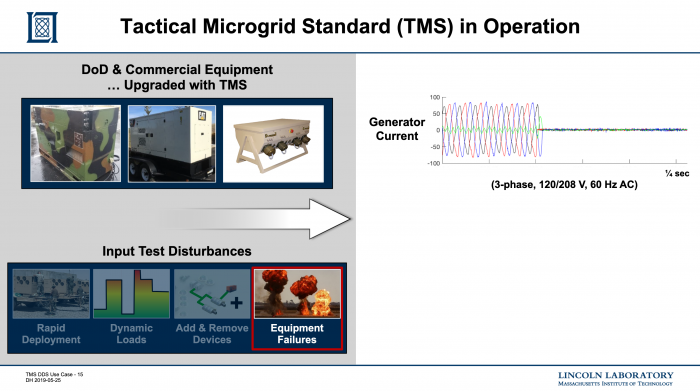 Figure 11: Tactical Microgrid Standard (TMS) in without TMS
Tactical Microgrid Standard (TMS) with TMS
Figure 12 represents the same traditional Spot Generation architecture with a TMS enhancements. When the Power Source (i.e., generator) stops producing electrical power, a battery backup starts to produce electricity almost immediately. Notice that the Grid Voltage hardly changes which allows the functionality includes mission and life critical systems as well as climate control and lights to continue working. In essence, TMS allows for a fail-over plan to take over. In this design a battery is in parallel with the generator. When a voltage drop is detected, the battery immediately starts providing backup power. The lines are a [daniel]hertz sinusoid to draw attention to the fail-over behavior of the Microgrid controller that instructed the battery to perform this service. The battery then did the fail-over internally and reported back the Microgrid control that the event had occurred and the Microgrid controller then has a few seconds to dispatch a new generator to pick up the slack.
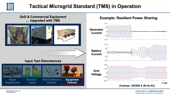 Figure 12: Tactical Microgrid Standard (TMS) with TMS
Final Remarks
Justification for making OMG DDS the Required Middleware in TMS
Data Distribution Service (DDS) is a key part in the success story for TMS. It is a key enabling technology and is the communications Middleware that helps create tie the components together. It also has an immediate benefit of creating modularity between components during integration. The proposed standard requires the use of DDS for defining publish and subscribe topics, the Datatype (i.e., structures) used in the topic and the Quality of Service (QoS) Policies. This requirement increases the confidence that all implementations will be compatible with the expected behaviors.
There were many other technologies middleware infrastructures considered for use in TMS. DDS stood out in several areas:
- OMG: Data Distribution Service (DDS) is a standardized communications middleware supporting modular software re-use
- Strong Technology
- Fully distributed publish/subscribe (pub/sub) and there is no central point of failure
- Machine-readable Interface Definition Language (IDL)
- Rich Quality of Service (QoS) allows for the tune it to support many different data flows.
- Interoperable wire protocol
- Security architecture provided a near term capability and an upgrade roadmap
- Healthy Ecosystem through the stable governance provided by Object Management Group® (OMG) and the various DDS vendors are working together to keep this as an Open Standard that improves over time.
- Open standard developed by an Standards Developing Organization (SDO)
- Stable open, transparent governance
- Multiple independent commercial implementations
- Continuous innovation
- Used across multiple industries so that the DoD or the power industry are not stuck with the whole bill
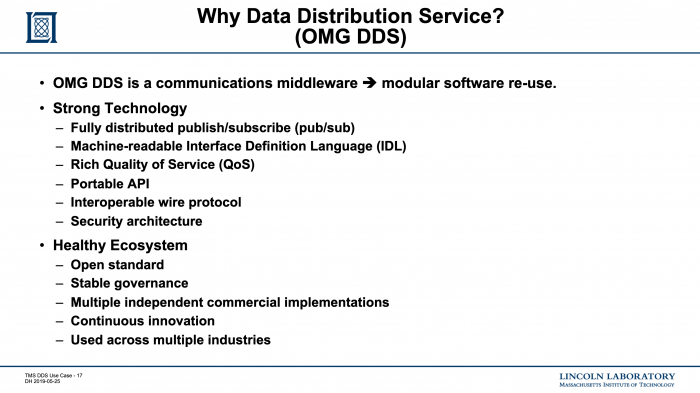 Figure 13: Justification for making Data Distribution Service (DDS) the Required Middleware in TMS
TMS Software Integration
Figure 14, depicts the interaction and roles of the Object Management Group (OMG), the Tactical Microgrid Standard (TMS) and the user's applications.
TMS provides Architecture artifacts:
- Portable Document Format (PDF) providing some human readable documentation about TMS: what things are; and how things work
- Interface Definition Language (IDL) providing machine readable information about the Topic, datatypes
- eXtensible Markup Language (XML) providing machine readable information about QoS and system configuration.
OMG provides DDS and related products artifacts:
- Portable Document Format (PDF) providing some human readable documentation about DDS and related tools: what things are; and how things work
- Interface Definition Language (IDL) preprocessor and other tools providing machine readable information used to autogenerate type support, topics and other things used in your application
- Software Library runtime library for the DDS products
Application provides the software focusing on the particular aspects of the Microgrid rather than the infrastructure required to run that software.
- Application Sources is Source Code written to solve a specific problem within the TMS Domain.
- Compiler(s) used to convert the Source Code to an Executable.
- Executable is the application code to be deployed on the Components, Devices on the Microgrid.
In summary, this provides a work flow of what TMS provides some things, DDS provides others, and a vendor of a TMS product make ther hardware and put their application on it. TMS application developer can focus on their application logic and build on top of the TMS and DDS provided communications and infrastructure.
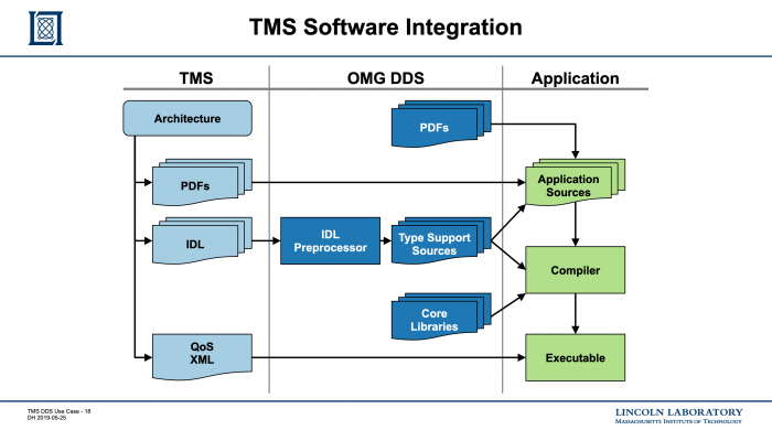 Figure 14: TMS Software Integration
Summary of DDS Adoption Experience
Figure 15 provides a list of Challenges and Takeaways during the adoption of Data Distribution Service (DDS) Middleware within TMS. So far, it has been a success story. Most of the partners that we have worked with are new to DDS. The faced a number of challenges, as they get started. At first there are questions about how much hardware is needed and what constraints does DDS place on their software?
Challenges
- Planning requirements
- Hardware: CPU, memory, and network - Data Distribution Service (DDS) Middleware does requires some more hardware
- Software: language, Operating System (OS), standard Middleware is more sophisticated than protocols that were developed during the 90's. However, for a modern system is fairly lightweight and efficient, so there has not been much resistance there.
- Getting started - There were many questions about how to get started
- Choosing an implementation - One of the strengths about DDS is there are many implementations, and that takes it a bit harder but we helped guide them through that.
- Finding beginner documents
- Navigating all the options - There are many parts to the standard and many options. Fortunately, TMS by providing an architecture along with a DDS implementation Guide, we were able to walk them through that material. And they were able to get started following the patterns we provided and apply some of what they learned from other applications.
- Terminology, DCPS object model
- Samples, keys, filters, buffers
- Event handling
- Debug and testing tools - We have been working with the OMG and the DDS Foundation to improve the debug and testing tools and documentation about the optional parts of the standard
- Optional parts of the standard
Takeaways
- Beginners surprised by
- Imposing size
- Steep learning curve
- Cost to start (time, effort, and money)
- TMS provides domain-specific
- Documentation, FAQ
- Tools
- Beginner response after code works
- Powerful capability
- Easy to extend and maintain
- Long path to mastery
- Plan to use DDS even more
In summary,we noticed better operation and maintenance capabilities for the defined end product. Do far, everyone has said they plan to use DDS not only in TMS but they are finding other applications as well.
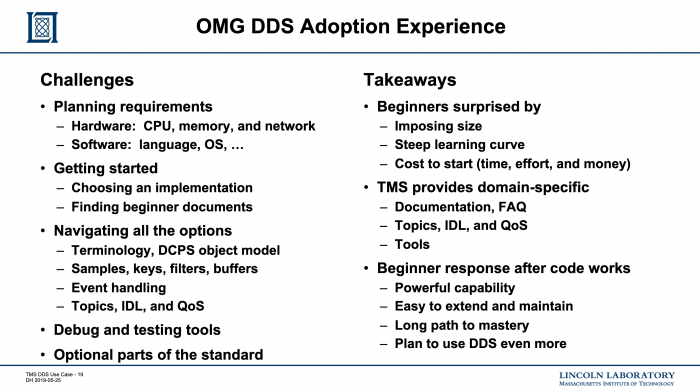 Figure 15: Summary of DDS Adoption Experience1)Puerto Rico Power Fully Restored 18 Months After Hurricane Maria Wiped Out the Grid, Weather Channel News, 21 March 20192)Resiliency of Power Grids After Earthquakes, John Eidinger, Alex K Tang G&E Engineering Systems Inc. and L&T Consulting, Olympic Valley, California, USA and Mississauga, Ontario, Canada3)Nearly 1 Million Customers To Lose Power In Planned PG&E Power Outages, NPR, National News, 27 October 20194)Ukraine's power outage was a cyber attack: Ukrenergo, Technology News, Reuters, 18 January 20175)Siemens, High-current industrial transformers, Acessed: 12 Jun2020, https://new.siemens.com/global/en/products/energy/high-voltage/transformers/high-current-industrial-transformers.html6)Foreign Humanitarian Assistance, Joint Publication 3-29, 14 May 2019, https://www.jcs.mil/Portals/36/Documents/Doctrine/pubs/jp3_29.pdf7)Critical Infrastructure Sectors, Cybersecurity and Infrastructure Security Agency (CISA), 24 March 2020, https://www.cisa.gov/critical-infrastructure-sectors
ddsf/public/guidebook/03_user/03_tms.txt · Last modified: 2021/09/02 19:43 by mitza